In an earlier article I talked in general terms about the benefits of using CAE tools to model the physics of manufacturing processes. In this article I will show a case study example using welding simulation to decide on the best strategy for welding a two-part swing arm together.
The objective is to compare two different clamping schemes with third iteration that uses tack welds to hold the parts together.
The two parts were made of carbon steel, welded along an ~80mm length using arc welding with an estimate energy input of around 2000J per centimetre.
The simulation tool used for this analysis uses a state-of-the-art multi-physics finite element programme as the underlying solver, but has a custom user interface that speaks to the manufacturing engineer about his process flow and not about the minutia of an FEA job set up.
Three scenarios were compared with a baseline condition without any clamping at all:
Scenario 1, Clamping both parts just during the welding phase.
Scenario 2, Clamping during welding and cooling.

Scenario 3, Use tack welds to secure the parts together.

The key results in this simulation are the overall distortion of the parts (measured as the maximum displacement away from the designed shape) and the residual stress in the part. Distortion affects manufacturing tolerances and can lead to scrap issues while high residual stresses can dramatically reduce the fatigue life of a part.
The results observed are tabulated below, you can see that the tack welding scheme gives the best outcome for both distortion and stress and this scheme also gives a lower cost of fixturing for the parts.


This example shows a clear benefit to the customer, and was achieved without any physical parts or try-outs in the manufacturing department which means the manufacturing scheme can be validated before parts are available or commissioned which can reduce the end-to-end design cycle.
 If you think this sort of simulation could benefit your processes, please get in touch. The solution supports laser and spot welding in addition to metal deposition type techniques.
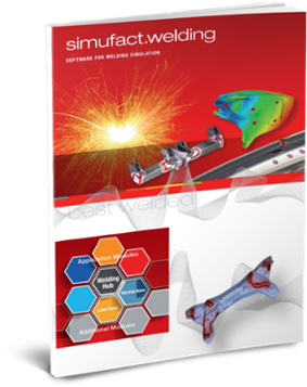
Download the whitepaper and find out why Simufact is the software for welding simulation >>
- Identify the optimal process parameters
- Avoid welding distortions and stresses
- Find answers to process stability issues
.png?width=139&height=70&name=DTE-Logo%20(4).png)
