.png?width=139&height=70&name=DTE-Logo%20(4).png "DTE Desktop Engineering")

It is for good reasons that designing laminated composite structures is sometimes known as a ‘black art’. It is not easy to intuit from the topology of and loads applied to a component what a good ply layup should be. Many companies rely on the wisdom of veteran engineers’ hard-won experience, but sometimes it is necessary to take a step back and ask “what else could we try?”.
Often the design of a composite layup starts with the definition of zones within a part. The layup on each of these zones can then be fettled using FEA to arrive at a stacking sequence which can then be used to define plies.
But how do you choose the zones? Is it arbitrary based on the topology of the part? Do you just chequer-board your panel into regular squares? You could use a technique developed with MSC Nastran for one of the F1 companies.
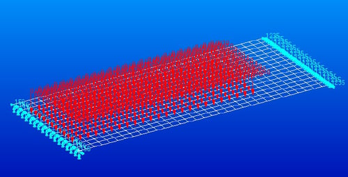 To illustrate the technique, we can use a simplified model of a rear wing spoiler. A half model is meshed with a symmetry boundary condition applied on the centreline and then a pressure load applied that comes from a CFD simulation.
A very simple stacking sequence is defined using three materials – a woven material at 0 o/45o, a UD at 0 o/45 o/90 o/-45o and a foam core material. The stacking order is ignored and the properties ‘smeared’ on each element.
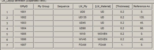
MSC Laminate Modeller is used to automatically generate a material instance for each element in the model and a design variable associated to the thickness of each layer – so 7 design variables per element in the model.
An optimisation is run in MSC Nastran with a global objective to minimise the mass of the structure and a constraint to keep the maximum deflection of the wing to <5mm. The results of this simulation are a thickness value for each layer of each element in the model. Plotting these results looks like this.
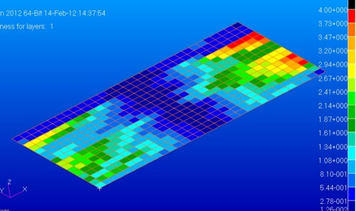
You can see regions that could be grouped together, but the values for each layer are arbitrary scalar ones and would leave you with a lot of manual effort in deciding how many repeats of a finite thickness pre-preg material to use in each element and then what your ply boundaries might look like.
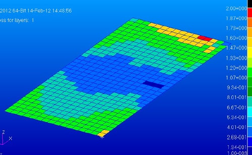
To address this issue MSC Nastran has a capability called “Discrete Variable Optimisation”. Essentially you tell Nastran what the allowable discrete values are (i.e. a nominal zero thickness and multiples of the pre-preg thickness). Nastran runs a normal optimisation sweep but then uses a Design of Experiments methodology on the final pass to choose a thickness value from the allowable list of values. The effect of this additional constraint on the quality of results is to give very clear indications of where ply/zone boundaries ought maybe to lie.
Clearly, there is still work to do from this point. The stacking sequence must be addressed in order to create a symmetrical layup. The boundaries may also need adjusting based on manufacturing constraints and ply drop-off rules. It might also be advantageous before this to run another optimisation using these zones where the nominal fibre orientations are varied to see if a better result can be obtained, leading potentially to mass savings.
The core optimisation functionality is available within the MSC One token licensing system while Laminate Modeller is an add-on. The Starter Edition enables smaller companies, without the huge budgets of an F1 team, to implement this sort of technique into their design process from about £8k per year.


Blog posts you may have missed on FEA >>