.png?width=139&height=70&name=DTE-Logo%20(4).png "DTE Desktop Engineering")

 This is the second part of an article on basic model checking.
In the first article we talked about some basic checks for the mass, stiffness and grounding integrity of the model.
In this article we’ll look at some static checks. In a simple or single component model these may not be necessary.
Inertia Load Checks
Our modal checks have already determined that the model is grounded in all six degrees of freedom, but we want to check that the reaction forces from a unit inertia load in X, Y and Z match the mass of the model. Believe it or not it is possible to build model that has a different mass effect in each direction if you have poorly connected DOF’s on an MPC or you have specified a mass matrix incorrectly on a 0D mass entity.
You would expect to see the reaction forces like this:
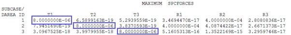
Where the force in case 1 is all in X, case 2 in Y and case 3 in Z, but with a badly specified coupled mass entity you could end up with this:

Which implies the mass is different in different directions. You can get the same effect with a poor choice of DOF’s on MPC’s connecting a lumped mass to the structure:
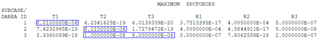
Here the Y and Z directions of the lumped mass have been incorrectly coupled meaning that for a load purely in Z we are getting reactions in the Y direction.
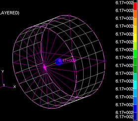
Unit Enforced Displacement Loads
In these cases, we need to tie all the constraint locations to a single node (a series of RBE2’s can be used) and then a unit enforced displacement is applied in each of the six DOF’s. We are expecting to see a displacement field for the structure that makes sense and nominally zero stress on the model. With this test we are again checking that badly connected MPC’s or springs aren’t causing stresses from rigid body motions of the model.
So what you should be looking for is this:
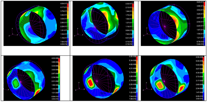
So in each case a fixed motion enforced at the grounding point gives a rigid body motion of the structure with stresses of the order of 10-11 to 10-9 MPa. But introduce a badly defined spring to the model where two non-parallel DOF’s are coupled and we get this:
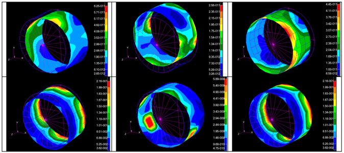
The stresses are low for the X,Y,Z and rY cases (~10-11) but for the rX and rZ cases we see stresses of 0.2MPa indicating a problem with the internal coupling of the model. Identifying where the issue lies can be helped by requesting strain energy output – in this example the strain energy in the failing cases is entirely within the spring element highlighting where the issue is.
Conclusions
These checks take time to do every time, but many times when running these on models submitted to support the client has already wasted days trying to understand the odd behaviour of their model. Automation can be your friend in these cases, clients have written scripts to set up these jobs using a standard set of headers with the bulk data for each new model. DTE have created a Patran routine for automatically setting up these jobs for you in seconds.
If you are working in an environment where traceablility of results is important, such as aircraft structures, naval architecture or nuclear facilities, then you might want to consider MSC SimManager as a data and process management environment to automate these checks and other analysis. This gives you a rigorous and searchable pedigree for the data and simulations used in your product design. Get in touch if you would like to discuss this or anything else.