.png?width=139&height=70&name=DTE-Logo%20(4).png "DTE Desktop Engineering")

In an earlier blog article the differences between kinematic and dynamic simulation were discussed, highlighting the importance of dynamic simulation as an input to the design of components by generating realistic loads. Most dynamics simulation is performed with the basic assumption that the components are rigid so only their mass and inertia properties are considered.
But this is not always an accurate assumption, although it does make for faster solution times. Consider the example below.
A company had used rigid body dynamics software to design an extending/retracting mechanism and the mechanical latch that held it in place. One of the load cases was a shock loading, designed to test that the latch would indeed hold the mechanism in its retracted condition, which was demonstrated successfully in the simulation.

*This geometry is a mock-up to demonstrate the effect and is not a representation of any client’s actual geometry
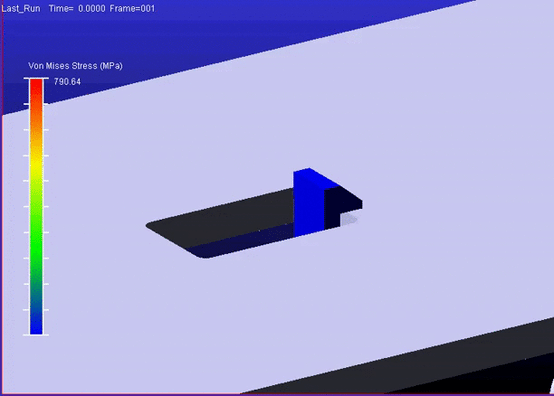
Loads were taken from the simulation and used to design the latch components using FEA. As weight was a consideration, the main latch member was weight reduced using an optimisation solution focussed on not exceeding maximum stress criteria.
Prototypes were manufactured and sent away for testing, where it was found that during the shock load condition the latch released the mechanism resulting in it deploying when it shouldn’t. On investigation it was found that while the latch mechanism itself was behaving as predicted by the motion simulation, but that the main latch member was flexing under load resulting in the observed behaviour.
Returning to their simulation model, the company introduced a flexible representation of the latch member generated from the FEA model and were able to reproduce the behaviour seen in test. This lead to a redesigned component, validated using flexible body dynamics, that resolved the problem.
*This geometry is a mock-up to demonstrate the effect and is not a representation of any client’s actual geometry
The lesson from this is that using dynamics simulation in system design should not be treated just as a concept design and loads generation tool, but should be used to validate the effects of as-designed component flexibility of intended performance.
In this example the tools used for the simulation were MSC Adams for the dynamics simulation and MSC Nastran for FEA. These tools are designed to work together with MSC.Nastran able to quickly generate a flexible body model from your FEA mesh which can be quickly integrated into your dynamics model.
Both these tools are available within the flexible MSC One token licensing scheme, which in its “Start Edition” packaging for smaller companies provides a remarkably cost effective way to bring simulation tools used by the world’s largest automotive and aerospace companies to your design process.
Andy Woodward
CEng. MIMechE
Analysis Consultant