Additive Manufacturing has been around in some form or other since the 90's when stereolitography (SLA) and selective laser sintering (SLS) techniques were used for rapid prototyping components, but with little strength or physical integrity there was limited utility from them.
3D printing of plastic parts can now be achieved on the desktop with a printer costing hundreds of pounds, but printing metal parts that could be used for load bearing applications has really come to the fore in the last few years with focus from industry and government on it as a cost-effective and short lead time manufacturing technique.
Simulating Additive Manufacturing Process
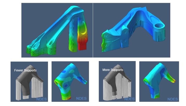
It is not without challenges to the engineer to use this process. The fusion of powder metals at high temperatures to an already cooling structure can lead to distortion and high residual stresses. Simple choices, like the orientation of a part in the build or the design of the support structure can have a big effect on part quality, measured as distortion.
The plots below show total distortion away from the designed shape comparing different orientations and support structures.
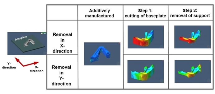
If you have residual stresses in the part, as printed with the support structure, then the order and direction in which you machine away the support structures can also effect the final distortion of the part.
Getting this right first time is not easy. A trial and error approach could take several builds to achieve an acceptable design at a not insignificant cost in machine time and project delay.
These effects can be predicted using CAE software, however to model this using classic analysis techniques is not an easy or quick thing. Taking a coupled structural/thermal approach with FEA might well result in solve times longer than the machine time needed to print a part unless a huge investment is made in parallel licenses and multi-cpu servers. On top of this the cost of characterising a material with phase change and temperature dependency is also prohibitively high.
There is a simple solution. Simufact AM can predict distortion and residual stress using technology based on the Marc Non-Linear FEA code. It uses a voxel type mesh created automatically from an imported STL file and an inherent strain material model that captures the thermo-mechanical behaviour of the material in a structural-only solution using simple measurements from test samples printed on your machine. Simufact AM simulates the build-up of the parts; using support structures either designed yourself or created automatically in the software.
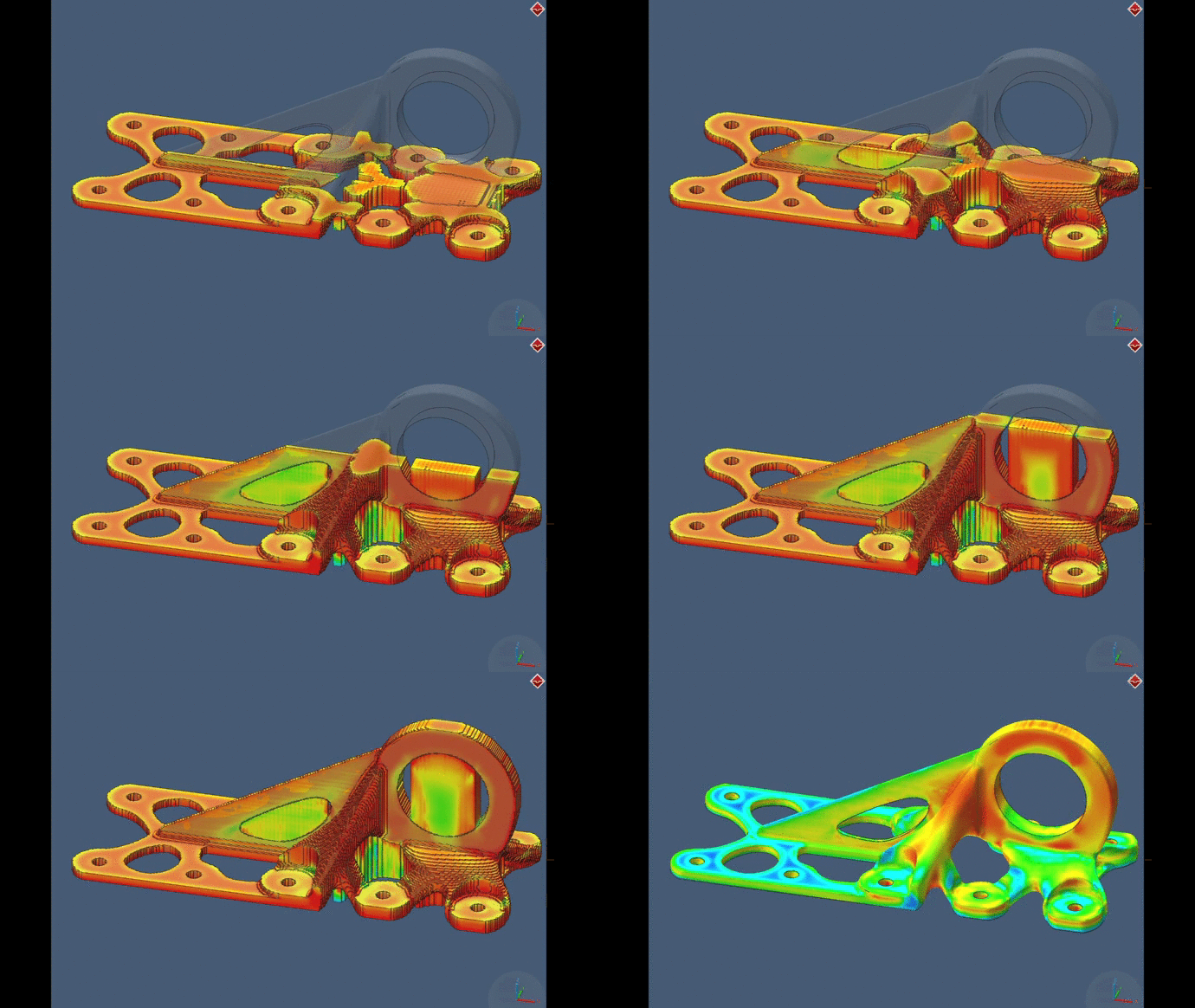
Subsequent operations, machining off support structures, heat treatment and hot isostatic pressing, can also be simulated.
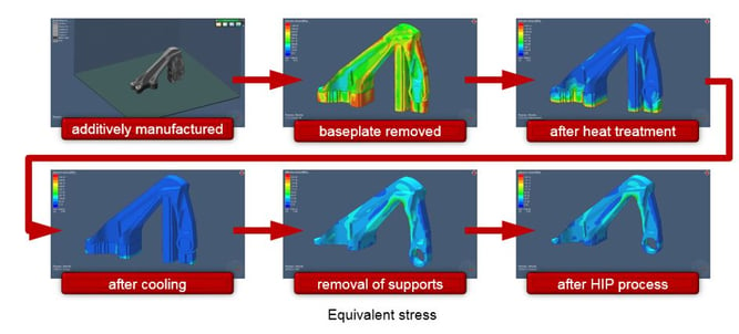
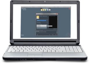
Best of all, Simufact AM does not require an expert in FEA to use it. The user interface is workflow oriented so a design or manufacturing engineer can pick it up easily and follow a familiar process to set up a virtual build. Runtimes are proportional to the fidelity of the voxel mesh but are very quick compared to both classic FEA and actual production builds.
If you would like to know more, or would like to see your part simulated, please contact us at DTE.
At DTE we can deliver an easy-to-learn process oriented Interface (GUI) that can be used to improve your 3D metal printing process.
Watch the 5 minute movie to see how easy it is to set up a simulation.
.png?width=139&height=70&name=DTE-Logo%20(4).png)

