.png?width=139&height=70&name=DTE-Logo%20(4).png "DTE Desktop Engineering")
 Blog")
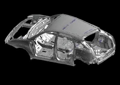
Topology Optimisation and 3D Printing

The use of FEA to design ‘optimal’ components has been around for nearly two decades. In general terms it works by meshing an available volume for a part and then eating away at the space iteratively to leave just those bits of the mesh that are doing work while aiming at a target mass for the part, as in the examples below.
Using this method ‘raw’ it is easy to see how un-manufacturable designs can result, so much effort has been invested by software developers to place manufacturing constraints on the optimisation process to, for example, eliminate voids or undercuts in moulded parts.
Topics: Automotive, Finite Element Analysis (FEA), Aerospace, Hexagon MSC Software
Welding Simulation

In an earlier article I talked in general terms about the benefits of using CAE tools to model the physics of manufacturing processes. In this article I will show a case study example using welding simulation to decide on the best strategy for welding a two-part swing arm together.
The objective is to compare two different clamping schemes with third iteration that uses tack welds to hold the parts together.
The two parts were made of carbon steel, welded along an ~80mm length using arc welding with an estimate energy input of around 2000J per centimetre.
The simulation tool used for this analysis uses a state-of-the-art multi-physics finite element programme as the underlying solver, but has a custom user interface that speaks to the manufacturing engineer about his process flow and not about the minutia of an FEA job set up.
Random Acoustic Loading

Working with long duration transient events in a finite element world can be extremely computationally expensive. If those events are very long, like the wheel hub forces over the lifespan of a vehicle, then it is impossible to simulate. One technique to overcome this limitation is to use something called Random Loading, or Random Analysis.
If a time signal can be considered properly random then it can be transformed from the time to the frequency domain and is known as a Power Spectral Density plot, or PSD. A quick check of randomness is that any section of a time history transformed in this way should give the same outcome as the whole signal. These PSD’s are best thought of as a statistical representation of the amount of energy in the signal as a function of frequency.
Virtual Loads Modelling
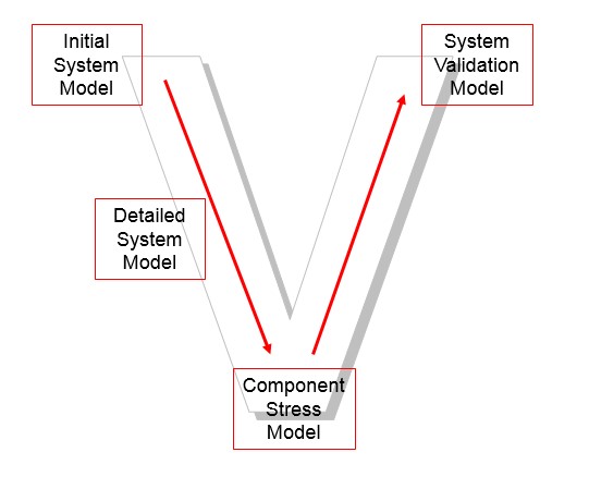
There are three key inputs to any finite element analysis process; the geometry representation as a mesh, the materials data and the loads. The validity of your decisions made from an analysis depends on capturing all of these accurately.
Accurate loading can be difficult to obtain. Some years ago we were involved in a project where the loads were provided by an OEM through a chain of suppliers. The stress results on the assembly indicated a catastrophic failure and no amount of tinkering with geometry and materials could go any way towards mitigating it.
Improve your 3D metal printing process
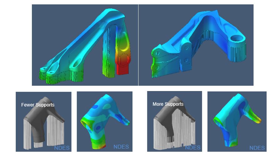
Additive Manufacturing has been around in some form or other since the 90's when stereolitography (SLA) and selective laser sintering (SLS) techniques were used for rapid prototyping components, but with little strength or physical integrity there was limited utility from them.
3D printing of plastic parts can now be achieved on the desktop with a printer costing hundreds of pounds, but printing metal parts that could be used for load bearing applications has really come to the fore in the last few years with focus from industry and government on it as a cost-effective and short lead time manufacturing technique.
Topics: Finite Element Analysis (FEA), Manufacturing, Hexagon MSC Software
Delamination Modelling
Delamination is one of the critical failure criteria in the design of laminates and any bonded joint. Modelling it with simulation software is possible, but can be very fiddly and labour intensive in many finite element codes. It is often necessary to pre-determine where delamination will occur and then create interface elements that capture the cohesive behaviour of bond. Doing this manually within a GUI environment is not fun.
The Marc finite element solver, from MSC Software, makes this very easy by having the solver detect where delamination is likely to occur between unique materials (or within a homogenous material) and then create the interface elements itself. This represents a massive saving in time for the FEA engineer creating these type of models.
Topics: Various - CAD CAM FEA PLM, Finite Element Analysis (FEA), Hexagon MSC Software
FEA Model Checking - Part 2
This is the second part of an article on basic model checking.
In the first article we talked about some basic checks for the mass, stiffness and grounding integrity of the model.
In this article we’ll look at some static checks. In a simple or single component model these may not be necessary.
Topics: Various - CAD CAM FEA PLM, Finite Element Analysis (FEA)
FEA Model Checking - Part 1
I’ve been an FEA user since 1992 and providing first line technical support for the last ten years. A surprising number of models sent to us over the years with ‘problem’ behaviour have had fundamental mistakes in the way they were constructed that could have been easily identified through systematic model checking.
In this two-part blog we will discuss some recommended model checks that can help identify basic problems. In the first one we’ll look at mass and stiffness checking.
Topics: Various - CAD CAM FEA PLM, Finite Element Analysis (FEA)
Non-linear Flexible body dynamics

In the last simulation blog the benefits of flexible body dynamics simulation were introduced.
The method used to represent a component flexibly requires an FEA solution that captures the vibration characteristics (normal modes) and the connectivity stiffness between the interface points (constraint modes). These are all linear modes used to represent any state of a component by a linear superposition sum. But what if your component doesn’t behave linearly?
Flexible bodies in Motion Simulation

In an earlier blog article the differences between kinematic and dynamic simulation were discussed, highlighting the importance of dynamic simulation as an input to the design of components by generating realistic loads. Most dynamics simulation is performed with the basic assumption that the components are rigid so only their mass and inertia properties are considered.
But this is not always an accurate assumption, although it does make for faster solution times. Consider the example below.