.png?width=139&height=70&name=DTE-Logo%20(4).png "DTE Desktop Engineering")
 Blog")
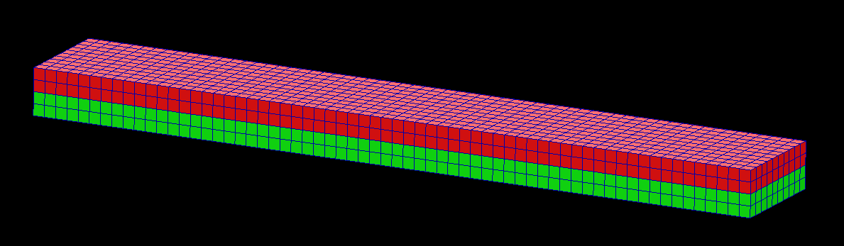
Non-uniform Thickness with MSC Apex
Capturing data
If you work with moulded or die cast parts you’ll be familiar with thin shell parts that have tapering thickness due to draft angles. Capturing this effect in your finite element mesh can be tricky and lead to approximations that might not be comfortable or conservative. MSC Apex has an auto-assignment feature that will accurately capture and represent the non-uniform shell thickness with remarkably little effort.
Topics: Various - CAD CAM FEA PLM, TechTips, Hexagon MSC Software
Defeaturing with MSC Apex

Prepping Computer-Aided Design (CAD) geometry for Finite Element Analysis (FEA) can be a complex, time-consuming and error-prone activity.
MSC Apex has been designed from the ground-up to make this a simple and intuitive step that can dramatically reduce the time spent in this part of the process, freeing highly qualified engineers to do more analysis and design improvement.
Topics: Various - CAD CAM FEA PLM, Finite Element Analysis (FEA), Hexagon MSC Software
Training Certification - why do it?
How do you get recognition of your skills or you want to be involved in better work or been seen as making a difference - how do you show your difference?
It’s all about having something unique that gives value to your employer.
Or if when job seeking how do you differentiate yourself from the rest of the pack? I had a friend who said you should draw pretty flowers on your CV! – whether he ever did that I don’t know, but in the competitive world we live you have to have a difference. That’s what sells. In sales jargon it’s called a Unique Selling Point, and when going for a job or looking to improve your position, that’s what you need.
Topics: Various - CAD CAM FEA PLM, Dassault Systemes, Training, CATIA
CATIA 3DEXPERIENCE contributes to 2 Construction Awards

The 3DEXPERIENCE platform from Dassault Systemes has played an important role in winning 2 awards in the Construction industry.
The Institution of Structural Engineers has awarded the 2017 prize for Construction Innovation to the team that designed and built The TallWood House at Brock Commons - an 18-storey mass timber hybrid building at the University of British Columbia (UBC) in Vancouver, Canada.
At 53m high, this student residence building has been recognized as the tallest mass timber hybrid building in the world. It is comprised of 17 storeys of five-ply cross-laminated timber (CLT) floor panels, glue-laminated timber columns.
Key to proving the construction process was the use of 3DEXPERIENCE to simulate the construction methods, from delivery of prefabricated parts to the work processes involved in assembling the building. CADMakers* used the 3DEXPERIENCE platform to simulate in real-time all these interactions and hence improve on methods in a digital world before committing to the real world.
See this video to compare the virtual with the real.
Zaha Hadid Architects used CATIA 3DEXPERIENCE as the platform for the design of the world’s longest asymmetrical single-stay bridge in Taiwan – The Danjiang Bridge. The design teams based in 3 locations across 2 continents used CATIA 3DEXPERIENCE On Cloud as the design and collaboration platform.
This greatly improved communication of ideas, management of information and enhanced the collaboration across the teams. The design team at Zaha’s were awarded the 2017 innovation in Collaboration Award from the Computing Construction Awards.
Read the full case study here >>
Both these awards show the gains that the construction industry can get from adopting the 3DEXPERIENCE platform as not only a 3D BIM tool but as a collaboration platform on which to store, control and manage all project data – meeting the requirements of BIM Level 3.
*VIRTUAL DESIGN MODELLING: CadMakers Inc

Topics: 3DEXPERIENCE, Architecture, Engineering & Construction, Various - CAD CAM FEA PLM, Building Information Modelling (BIM)
Understanding the risks in the aerospace supply chain

As consumers around the world are demanding greater access to air travel, this has led to orders for 38,000 new aircraft. Although this represents the potential for significant revenue, OEMs and suppliers face significant risks that they must overcome in order to develop these aircraft cost effectively and ensure a quick time to market.
A major trigger of these risks is how OEMs are now tasking suppliers with designing aerospace parts in addition to manufacturing.
Topics: Various - CAD CAM FEA PLM, Aerospace
OEM customers benefit from proven integration experience & expertise for Stage V transition
Attempts by the European Commission to reduce air pollution poses new challenges for engine manufacturers in the form of Stage V emissions standards. Many manufacturers can use their knowledge and experience with on-road developments to ensure off-road engine developments work efficiently.
Following on from our previously published Stage V emissions article and discussions around tougher standards for more engine types; After-treatment systems for smaller engines; and DPF in the after-treatment system, John Deere has become one of the first to release their developments.
Topics: Various - CAD CAM FEA PLM
Composite Zoning Optimisation

It is for good reasons that designing laminated composite structures is sometimes known as a ‘black art’. It is not easy to intuit from the topology of and loads applied to a component what a good ply layup should be. Many companies rely on the wisdom of veteran engineers’ hard-won experience, but sometimes it is necessary to take a step back and ask “what else could we try?”.
Often the design of a composite layup starts with the definition of zones within a part. The layup on each of these zones can then be fettled using FEA to arrive at a stacking sequence which can then be used to define plies.
But how do you choose the zones? Is it arbitrary based on the topology of the part? Do you just chequer-board your panel into regular squares? You could use a technique developed with MSC Nastran for one of the F1 companies.
Topics: Various - CAD CAM FEA PLM, Finite Element Analysis (FEA), Hexagon MSC Software
Are Alternative Facts acceptable to an Engineer?

We are currently in a place called “post-truth era” where “alternative facts” are being positioned as acceptable currency. I was wondering how this impacts an engineer who must work with the laws of nature and harness them for the good of mankind.
A key lesson we all learn during our engineering education and working experiences is that the mechanical psychical world obeys Newtons Three Laws of Motion.
These laws have the laid the foundation for classical mechanics upon which engineers have built the knowledge and hence technology that has delivered cars, aeroplanes and got mankind to the moon.
Topics: 3DEXPERIENCE, Various - CAD CAM FEA PLM, CATIA
Delamination Modelling
Delamination is one of the critical failure criteria in the design of laminates and any bonded joint. Modelling it with simulation software is possible, but can be very fiddly and labour intensive in many finite element codes. It is often necessary to pre-determine where delamination will occur and then create interface elements that capture the cohesive behaviour of bond. Doing this manually within a GUI environment is not fun.
The Marc finite element solver, from MSC Software, makes this very easy by having the solver detect where delamination is likely to occur between unique materials (or within a homogenous material) and then create the interface elements itself. This represents a massive saving in time for the FEA engineer creating these type of models.
Topics: Various - CAD CAM FEA PLM, Finite Element Analysis (FEA), Hexagon MSC Software
FEA Model Checking - Part 2
This is the second part of an article on basic model checking.
In the first article we talked about some basic checks for the mass, stiffness and grounding integrity of the model.
In this article we’ll look at some static checks. In a simple or single component model these may not be necessary.
Topics: Various - CAD CAM FEA PLM, Finite Element Analysis (FEA)